Rapid Prototyping with MacroFab, Part 2
As I described in Part 1, I am using MacroFab for rapid prototyping of my jeepbot concept project. In this post, I’ll describe the next phase of my project and how MacroFab has made it easy to get there.
As I thought about what jeepbot should be, the concept evolved into several different ideas. What I wanted to build first was a control board that directly controlled a simple relay box, like the one described by Hooz’s DIY project post. The idea was to focus on the control circuitry first, rather than the relay circuitry. The control board would replace a bank of switches, so easily plug-and-play. This would allow me to fine-tune the design over time, while retaining a good, simple relay box in the vehicle. I also renamed the project concept switchbot to go with the idea of being vehicle independent.
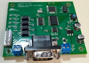
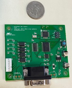
For my first board, I designed a circuit that contained a Atmel ATmega328P micro-controller, a MCP2515 CAN controller, a MCP2551 CAN transceiver, and a 74HC595D 8-bit shift register. I only designed in 4 switch circuits for this initial board. Each switch circuit is protected by a LTV816 optocoupler, to isolate the micro-controller’s digital logic from the actual switches. These output lines can in turn be used to drive other circuits, such as a relay board.
To round out the board, I added a two-port terminal connector for +12v power and ground, a two-port terminal connector for CAN high and low connections, and a DB9 connector for easily interfacing into automobile OBD-II connectors. I used a 6-port Molex connector for output for power, ground, and the 4 switch channels. A reset button and a 2x3 header for in-system chip programming (ICSP) interface to program the ATmega micro-controller was important to make sure I could download firmware later.
The board also has a simple +12v to +5v power supply regulation circuit and protection diode, but not with significant automotive transient protection. That circuitry will likely be needed in future versions.
You can find the Eagle files for this version of the board on github at https://github.com/dcgibbons/switchbot/releases/tag/v1.0_alpha
Like with my previous board, I used the MacroFab web interface to upload my Eagle design files. This board had a lot more parts than my previous one, and my experience with the previous board taught me I needed to be more careful in double-checking my part selection. Even with my caution, the engineers at MacroFab found several discrepancies for me to clarify, mostly with resistor values.
While the board was being produced, I discovered the diode value mistake I made with my previous board. I found the same mistake in this board, so I asked MacroFab if it could be replaced - yep! And they did so easily, since this was before assembly of the board had actually begun.
During the final assembly of the board, MacroFab found the two-port connector parts I selected for my CAN and power interfaces were wrong for my board design. I asked them not to populate those connectors as I had many of the correct ones in my workshop.
MacroFab also found during assembly that the crystal oscillator part I had selected would not match the pins exactly on my board. The size was correct, but the orientation was wrong. I recall that selecting the oscillator part was difficult, so I was not too surprised. A little bit more research from the parts houses and I found what I thought would be a better part. MacroFab agreed and ordered it for me. This extra order only added a couple of days to the overall board assembly time.
 A
couple of weeks after ordering, my boards arrived. I ordered two of the boards
this time, as I wanted to be able to leave one in my
Jeep and use another for bench testing. As soon as
they arrived, I hand soldered in the two-port connectors I had (I have a nice
supply of them from SparkFun as
they are so commonly used on Arduino-based boards).
The next step was to power up the board and see what happens. No smoke; it lives! Without a program downloaded to the micro-controller nothing much happened, but the solid power-on LED and the all 4 switch LEDs being on indicated to me that the core of the system was alive.
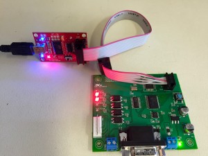
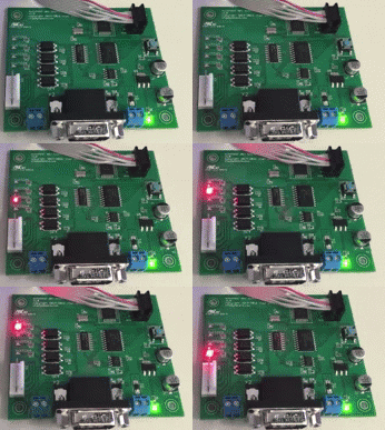
Next I used an AVR ICSP programmer to download software using the Arduino IDE, which front-ends the avrdude tool. I picked the Arduino blink sketch to see if it would download… success! I do not have an LED on pin 13 of the ATmega so I couldn’t see the sketch actually running, so next I dowloadeded my shiftreg test sketch. This sketch will cycle through all 4 switches and leave each one active for a few milliseconds. It will also display anything it receives over the CAN bus to its own serial output, although I did not make it easy to show serial output on this board.
Surprisingly to me, not only did the sketch download, it actually worked. The switch indicator LEDs lit up in turn, and with a meter I could measure the signal voltage on each output line on the Molex connector. Success!
I now have the basis for real hardware testing in my vehicle. I’ll post a follow-up on further progress with this project.
The most amazing thing about this experience so far has been the ease of use of the MacroFab interface, their quick turn-around time, and the pricing. For these two boards, the price was approximately \$76 each. For a hobbyist, this pricing puts real low-volume projects in easy each. At higher quantities, the price drops dramatically. For 1,000 units, for example, pricing approaches $15 a board for this design.
Stay tuned…


