CAN Bus Hacking with the Arduino and Raspberry Pi
In December of 2013, I published a set of videos on YouTube discussing how to do CAN bus hacking using an Arduino and/or Raspberry Pi. These videos were made in conjunction with my Jeep hacking projects.
Several viewers have asked for a little bit more information on getting an Arduino and Raspberry Pi to talk to one another over a CAN bus, so I thought I’d provide a bit of written information here to accompany the videos. In addition, two years of time have provided some improvements that make everything easier.
For both the Arduino and the Raspberry Pi, I used daughter boards that use Microchip’s MCP2515 CAN controller and MCP2551 CAN transceiver. These are extremely common integrated circuits for CAN and are great to integrate with as they use an Serial Peripheral Interface (SPI).
The Videos
The CAN Bus
A CAN bus has to be properly terminated on each end of the bus. The easiest way to do this on a bench is using a breadboard. Use two 120 Ω resistors on each end of one of the power rails to terminate the bus properly. You can then connect your nodes to any location within the power rail and have them join the bus properly.
Be sure to create a twisted pair out of each set of wires coming from each node. CAN bus is highly resilient to electrical noise when each node follows certain rules, and twisted pairs of wires is one of those rules.
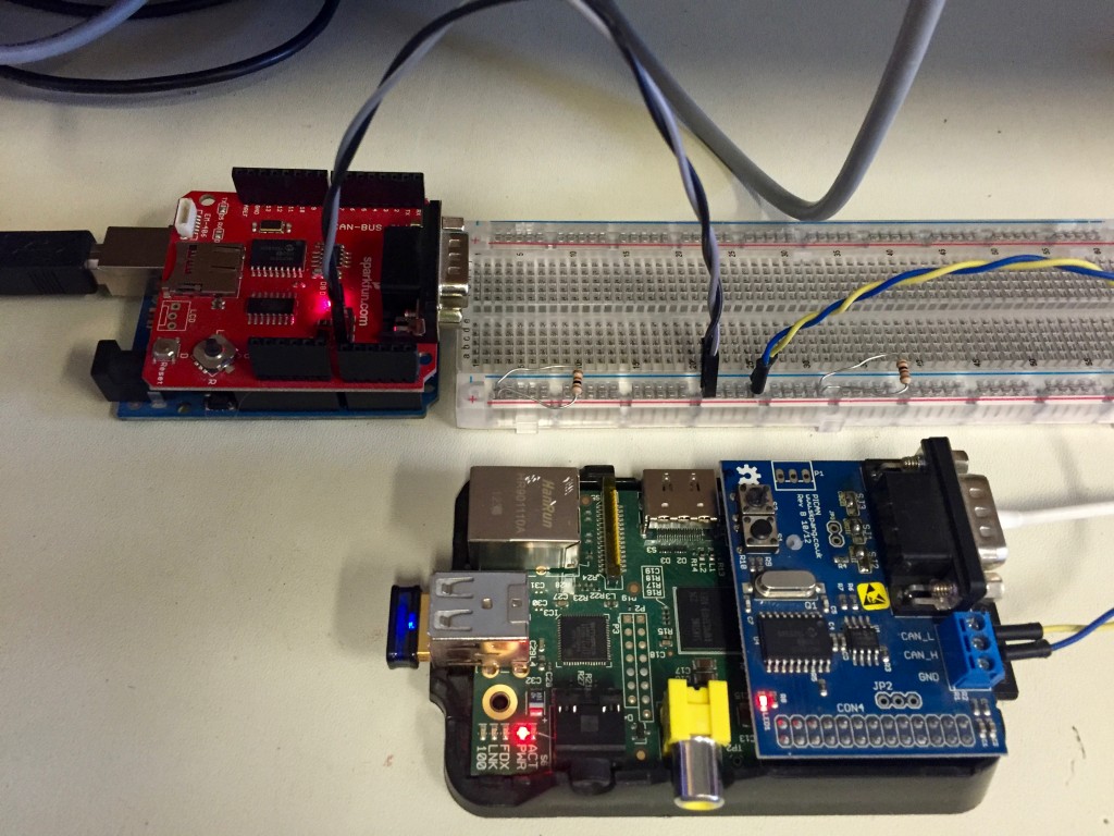 A CAN bus setup on a breadboard
The Arduino Setup
Sparkfun sells a CAN bus shield designed by SK Pang. This shield is great for developing automotive-focused applications, and is extremely easy to use from a software standpoint. Once built, the shield plugs into an Arduino with no further configuration.
For software, the following should be downloaded:
- My AVRDebug library - https://github.com/dcgibbons/AVRDebug
- My “hello, world” application - https://github.com/dcgibbons/CANBusHello
- The library for the Sparkfun / SK Pang shield - https://github.com/sparkfun/SparkFun_CAN-Bus_Arduino_Library
Once built and downloaded, the project will broadcast a message to the CAN bus every 500ms. The message will contain an ASCII string value of a monotonically increasing integer value.
If you run the project without another node connected to the CAN bus, expect to start seeing errors after a few messages are queued up. The sender requires another node on the network to acknowledge the message electrically. This can trip you up if you are first starting out with the CAN bus as it is non-obvious why you might be getting an error.
The Raspberry Pi Setup
The easiest way to get CAN support on your Raspberry Pi is to buy a daughter board from SK Pang: thePICAN board. You can build your own configuration using mcp2515 and mcp2551 ICs, but for the price the PICAN is an easy bet.
Today the Raspberry Pi setup is much easier than ever before. Pick the 2015-02-16 or newer version of Raspian and you will not have to compile any kernel modules.
See this blog post on SK Pang site on setting up your complete system.
On the RPi, the regular SK Pang setup they have documented works great. On mine, the end of my /boot/config.txt looks like:
dtparam=spi=on dtoverlay=mcp2515-can0-overlay,oscillator=16000000,interrupt=25 dtoverlay=spi-bcm2835-overlay dtoverlay=spi-dma-overlay
and then my /etc/network/interfaces file looks like:
auto can0 iface can0 inet manual pre-up ip link set $IFACE type can bitrate 500000 listen-only off triple-sampling on up /sbin/ifconfig $IFACE up down /sbin/ifconfig $IFACE down
The ip command can give you a big clue on state if you use this command:
root@raspberrypi:~# ip -details -statistics link show can0
3: can0: <NOARP,UP,LOWER_UP,ECHO> mtu 16 qdisc pfifo_fast state UNKNOWN mode DEFAULT qlen 10
link/can
can <TRIPLE-SAMPLING>
**state ERROR-ACTIVE**
restart-ms 0 bitrate 500000
sample-point 0.875 tq 125 prop-seg 6 phase-seg1 7 phase-seg2 2 sjw 1
mcp251x: tseg1 3..16 tseg2 2..8 sjw 1..4 brp 1..64 brp-inc 1
**clock 8000000** re-started bus-errors arbit-lost error-warn error-pass bus-off
The couple of things I bolded are key. The clock should be 1/2 of what the oscillator setting in config.txt is (weird quirk). The state is the actual MCP2515 state - so error-active is what you usually want to see. Error-passive or Bus-off are bad. See the mcp2515 datasheet for details there.
You’ll want can-utils downloaded and installed: https://github.com/linux-can/can-utils
Then, if you run the Arduinoo project so it’s sending data every 500 ms, and then run this command on the RPi, you should see some similar output:
pi@raspberrypi ~ $ candump -t a -c -c -a can0
(1452184714.419422) can0 1FF [8] 31 34 32 35 33 00 00 00 '14253...'
(1452184714.939332) can0 1FF [8] 31 34 32 35 34 00 00 00 '14254...'
(1452184715.459257) can0 1FF [8] 31 34 32 35 35 00 00 00 '14255...'
You can use the can-utils for just about everything. cansend and canplayer are useful for sending messages, candump and cansniffer are the two used for watching data (cansniffer is especially awesome for figuring out what’s really happening). If you want to write custom software that uses CAN on the RPi, then you can use these as examples. It’s effectively just using the socket system calls.
So that’s pretty much it. You have to have the bus speed match, you have to have the correct wiring, but otherwise that’s all there is to it. I’ve got a setup with an Arduino as shown below, the RPi as shown below, another RPi with a different CAN board (still mcp25xx), and a breadboard cased ATMEGA setup without the Arduino hardware. All works great.