Rapid Prototyping with MacroFab, Part 1
As part of my jeepbot project, I wanted to build some printed circuit boards (PCBs) to test the concept, try out different designs, and generally just have a real solution. I learned quickly that going from LEGO-style building blocks based on Arduino boards to my own PCB was another learning curve with a lot of unknowns. There are certainly plenty of tutorials online for designing boards, board houses for building them, etc., but it certainly wasn’t an easy or inexpensive job for those learning how to build. As a result, my project languished a bit as both my day job became more demanding (and amazing, rewarding) and the work effort for this project began to look larger and more complicated than I had anticipated.
Around this time, a former co-worker founded MacroFab, a company geared towards solving the problem of making it easier for small “makers” (like me!) to “go from prototype to market faster than ever before.” MacroFab’s promise is to make it fast, easy, and cheap to create prototypes, and then make it easy to move into the market easily. Macrofab will even manage production and inventory for you!
While the market support is very intruiging for turning my project into an actual product, at my project stage I was mostly interested in Macrofab for the prototyping aspect of it. Given I had almost zero experience designing schematics, creating boards, or really anything related to creating hardware, I wanted something easy and inexpensive, as I was sure to be making a lot of mistakes.
I decided to make a small board to test out everything. I really didn’t know what to expect when trying to create a real board, so I stuck with something very simple and easy to test: a +12v to +5v power supply. The design I picked was simple: a circuit based on a NCP1117 linear voltage regulator, along with a DC barrel plug for input power, a diode to keep everything safe, a header for the output signals, and a green power-on LED for good measure.
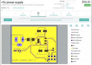
MacroFab’s interface starts off with you creating a new project, and then uploading your design either directly from your design tool, such as CadSoft’s Eagle, or from raw industry standard file formats. Since I’m using Eagle, that was an easy choice.
 After
your files are uploaded and their system processes them, you are presented
with a view of your PCB and all of its layers. You also start getting a cost
estimate on your design based upon the PCB price, the parts, and MacroFab’s
own labor costs. As you can seen from the screenshot, this board costs less
than $17 for a quantity of 1. Absolutely amazing.
 The
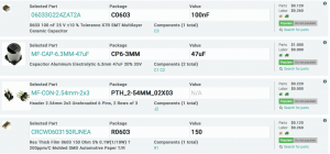
next step in the process is going through your bill of materials. As I learned
later, this is the part of the process where you need to pay the most
attention. MacroFab’s software will do a decent job of finding parts for you
based on your design files. However, not all parts can be found all of the
time and you will need to double-check that the parts match your design
correctly.
One thing that MacroFab has done is a huge benefit here: they have their own house parts, and an Eagle library to make selecting them easy. For common things such as resistors, capacitors, LEDs, common micro-controllers, headers, etc. these are a slam-dunk. Not only are the parts guaranteed to be on-hand, they’re usually a lot cheaper, too. And for someone like me, I’m not particularly interested in the nuances of picking the absolute “best” part available; I want good-enough, available, cheap, and easy. Are there better LEDs than the ones in MacroFab’s inventory? Maybe, and you can get them if you want, but I’m not sure why I would spend any time looking for them. Can you tell I’m not a hardware engineer?
The final step in the MacroFab interface before ordering is to review the placement of the parts you’ve selected. Here’s your final chance to review, and it gives you a visual indication of how the parts will be placed on the board. It’s pretty easy to see if you’ve picked a through-hole part instead of a surface-mount, for example, so this step is amazing valuable and easy.
Finally, you order your part and MacroFab’s operations take over. Within a day or two of submitting your order, MacroFab’s engineers do a sanity check on your design. In my case, they wanted to verify that I had the right resistor and diode values in my design - I said yes (which later turned out to be wrong!) - and off they went to producing the board.
MacroFab doesn’t create its own PCBs - that’s a cut-throat business with little margin - so they send out for PCBs from other vendors. At the same time, they order any parts they might need for your design if they do not already have the parts in stock. Once everything is in stock, they do the final assembly of the board in house. With all three of the boards I have had them build so far, there have been little issues at this stage of the game, all related to my own mistakes.
In this case, the DC power plug part I picked had the wrong type of through-hole connectors. Whoops! As a newbie, I didn’t have enough attention to detail when I was selecting that part (MacroFab’s interface couldn’t find the right one for me automatically). No matter, I had a bunch of those in my workshop at the house, so I asked them to skip placement of the part.
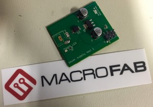
 About
two weeks (during the busy holiday season, no less!) after I submitted my
order, my board arrived. Included were the spare parts from my order and the
assembled board itself. How exciting, my first PCB ever! As someone who
started out with electronics and hardware as a kid, but quickly moved to
software, this was hugely satisfying and made me wish I had done it decades
ago.
You’ll notice the couple of hand-solder marks on the outline for the DC barrel jack that I made. It turns out I didn’t have the right part in my workshop after all, so I just soldered some wire leads to the pins to test everything out. And, it didn’t work! Puzzled, but not surprised, I did some quick analysis. It turns out my diode was not the right voltage rating. Instead of a maximum of 100v, it had a pass-through voltage of 100v instead of 12v… whoops!
Once I bypassed that diode, the circuit worked great, except for my LED not lighting up. I quickly found that I had selected a 150K Ω resistor instead of the 150 Ω resistor I needed. MacroFab actually caught this mistake, but I told them the part was the right one. D’oh!
Regardless, my first experiment was a success. For less than $20 delivered, I had my first PCB design built and I learned a great deal about the process. All of which made it much easier to do my next project, and the goal of all of this - the intelligent switching board for my Jeep. See part 2 for more details on the next phase.